
 Toyota Camry et,
Toyota Partner.
Toyota Camry et,
PIECES CONSTITUTIVES
SCHEMA
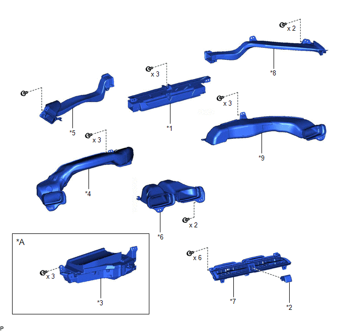
|
*A | avec affichage Headup |
- | - |
|
*1 | ENSEMBLE DE BUSE DE DEGIVREUR |
*2 | ENSEMBLE DE CONTACTEUR DES FEUX DE DETRESSE |
|
*3 | SOUS-ENSEMBLE DE RETROVISEUR DU COMBINE D'INSTRUMENTS |
*4 | SOUS-ENSEMBLE DE CONDUITE DE CHAUFFAGE A REGISTRE N° 1 |
|
*5 | CONDUITE DE BUSE DE DEGIVREUR LATERALE N° 1 |
*6 | SOUS-ENSEMBLE DE CONDUITE DE CHAUFFAGE A REGISTRE N° 2 |
|
*7 | ENSEMBLE DE REGISTRE DE TABLEAU DE BORD N° 2 |
*8 | CONDUITE DE BUSE DE DEGIVREUR LATERALE N° 2 |
|
*9 | SOUS-ENSEMBLE DE CONDUITE DE CHAUFFAGE A REGISTRE N° 3 |
- | - |
 Depose
Perte de la communication avec le capteur de distance avant du régulateur de vitesse (U0235)
DESCRIPTION La caméra de reconnaissance de marche avant communique avec l'ensemble de capteur radar à ondes millimétriques via la communication CAN. En cas d'erreur de communication avec l'ensemble de capteur radar à ondes millimétriques, la caméra de reconnaissance de marche avant enregistre ...
Tableau Du Mode De Securite
TABLEAU DU MODE DE SECURITE En cas de problème dans le système de direction assistée, l'assistance de direction s'arrête ou la quantité d'assistance de direction est réduite pour protéger le système. Système de direction assistée
Dysfonctionnement Fonctionnement du mode de sécuri ...
Pieces Constitutives
PIECES CONSTITUTIVES SCHEMA
*1 JOINT TORIQUE DE MAITRE-CYLINDRE DE FREIN
*2 SOUS-ENSEMBLE DE MAITRE-CYLINDRE DE FREIN
*3 CANALISATION DE FREIN
*4 CONNECTEUR
*5 ENSEMBLE DE SERVOFREIN
- -
Couple de serrage pour "zones principales ...

